9.1 Introduction

Pipes, which are operated at ambient temperatures, lose heat, regardless of how well the pipe is insulated. Trace heaters are used to raise or maintain the temperature of a product in the pipe, to protect it from frost, or to compensate for heat loss.

It is possible to distinguish between two types of trace heaters – Electrical or steampowered. Trace heaters that use steam have an advantage over electrical heaters in that they are more cost effective to operate and can be used in hazardous areas without any problem. This chapter only deals with steam-powered trace heaters.

The design of a steam trace heater depends on the system so – depending on the heat loss – one or several smaller steam pipes (tracers) are laid along the product pipe and around, valves and fittings. The way in which the heater is fitted generally has a considerable influence on the heat output of a trace heater. The average thermal outputs are given in W/m K for some technical designs. This book does not deal with the details of how heat loss is calculated and how to specify the number of tracers. The calculation method is only explained using an example. For day-to-day practical purposes the number of tracer heating pipes is calculated on the basis of values established from past experience and tables for some operating situations checked in practical situations. This chapter also discusses the technical design of trace heaters and the selection of traps for some applications.

9.2 Trace heater classes

The required steam pressure and the number of tracers required to provide frost protection or for product trace heating are determined in different ways. When it comes to product trace heaters a distinction is made between light, medium-duty and heavy-duty trace heaters. Space heating is often advisable for certain purposes. The characteristic of a space heating system is that there is no direct contact between the tracer and the pipe. Heat is primarily transferred by radiating heat to the still air in the space between the pipe and the tracer. The air in turn transfers heat to the pipe by means of convection.

Trace heater classes:

  • Frost protection: To prevent pipes from freezing, holding temperature 10 ºC.
  • Space heating: Pipes with sensitive media (e.g. measuring lines), holding temperature 10 ºC.
  • Light product trace heater: Raise and maintain temperature/below 30 ºC.
  • Medium-duty product trace heater: Raise and maintain temperature/between 30 ºC and 80 ºC.
  • Heavy-duty product trace heater: Raise and maintain temperature/above 80 ºC.

Copper, steel and stainless steel are materials of a suitable quality for tracers. The diameters generally used are 12 mm for copper and 15 mm for steel. The holding temperature is so critical on some products that conventional trace heaters cannot fulfil these criteria adequately. Heat transfer paste is used in such cases. In contrast to normal trace heaters, the tracer here is fitted on the top of the product pipe and the contact surface with the pipe wall is increased several times through the use of heat transfer paste. There are process situations where a steam jacket heating system around the process pipe is the best solution (jacket heating or jacketing). 

9.3 Heat requirement of a pipe

The calculation of how much heat is lost by a pipe is based on the following formula: 

[1], [2], [3] WAGNER, W.: Wasser und Wasserdampf im Anlagenbau. Vogel Buchverlag, Wurzburg, 2. Edition, 2011

The heat transmission coefficient is dependent on the coefficient of heat transfer (i ) between the product and the pipe wall, the thermal conductivity (1, 2, 3) of the pipe wall, insulation and of the plate and the heat transfer coefficient (a) between the insulation plate and the ambient air – see Fig. 9-1.

Fig. 9-1: Heat transfer factors

Fig. 9-1: Heat transfer factors

Sample calculation:

Where the lowest outside temperature T2 is -15 ºC, the 40 m long oil pipe DN 250 must be kept at a temperature T1 of 50 ºC. ∆T = 65 K

Heat transfer coefficient, oil to pipe wall αi = 500 W/m2 K

Heat transfer coefficient, insulation plate to air αa = 10 W/m2 K 

Pipe DN 50

Inner diameter d1 = 260.4 mm

Outside diameter d2 = 273 mm

Thermal conductivity λ1 = 60 W/m K

Insulation

Insulation thickness s1 = 100 mm

Thermal conductivity λ2 = 0.06 W/m K

Aluminum insulation plate  

Wall thickness s2 = 1.2 mm

Thermal conductivity λ3 = 200 W/m K

Calculation objective:

 Heat loss  of the pipe 

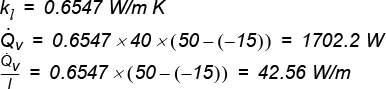
In order to keep the oil pipe at 50 ºC when the outside temperature is -15 °C, compensation of 1702.2 W (42.56 W per running meter) is required from the trace heater tracer pipe.


9.4 Heat output of a trace heater

In order to prevent unacceptable cooling of a product pipe, the same amount of heat must be supplied by the trace heater as is lost through the insulation. It must be remembered that only part of the tracer surface loses heat through radiation but, in the space between the tracer and the pipe, heat is transferred through convection. In addition to this, part of the tracer surface is covered by insulation and cannot contribute effectively to heat transfer. What the above information means is that the heat output factors depend on how the tracer is fitted.

  • Space heating, Fig. 9-2: With this form of heating the tracer does not make contact with the product pipe and heat output is by means of convection. Average heat output is 0.35 W/m K.
Fig. 9-2: Space heating

Fig. 9-2: Space heating

  • Partial space heating, Fig. 9-3: The tracer is in relatively close contact to the product pipe. Heat output is only partially via the product pipe. Heating has an average heat output of 0.7 W/m K
Fig. 9-3: Partial contact heating

Fig. 9-3: Partial contact heating

  • Contact heating, Fig. 9-4: Almost complete contact between the tracer and the product pipe is achieved through the use of clamping bands. The maximum distance between bands is 600 mm. Heat output is almost exclusively via the product pipe. Average heat output is 1.1 W/m K.
Fig. 9-4: Contact heating

Fig. 9-4: Contact heating

  • Heating via heat transfer paste, Fig. 9-5, for the heavy trace heating. In order to increase the transfer of heat between the tracer and the product pipe, in addition to the clamping bands the heat conduction area is increased through the application of heat transfer paste. The average heat output can increase up to 5 W/m K.
Fig. 9-5: Tracer with heat transfer paste

Fig. 9-5: Tracer with heat transfer paste

9.5 Calculating the number of tracers

As has already been mentioned, heat losses will not be calculated in detail here. The scope of this chapter should be sufficient to calculate the heat losses on the basis of values established from practical experience and using tables, Fig. 9-6 to Fig. 9-9. The tables are adjusted to steam pressure of 3.5 - 5.5 - 8.0 - 10 bar and for DN 15 steel tracers and DN 12 copper tracers. It is generally true that the saturated steam temperature must be at least 30 Kelvin higher than the required holding temperature.

Example: To keep the product temperature at 140 ºC, steam pressure of 8 bar (170 ºC) should be used for heating.

Tables

The left-hand column of the table indicates the holding temperature in ºC. The right-hand column “L” shows the maximum length of the tracer and “H” shows the maximum height difference, i.e. the number of metres which the tracer is allowed to rise (static head).

One tracer is sufficient for the areas in the table with a light-blue background (1). Two tracers are required for the areas (2) with a dark-blue background and three tracers are needed for the grey area (3). 

Fig. 9-6: Approximated calculation of the number of tracers with steam pressure of 3.5 bar

Fig. 9-6: Approximated calculation of the number of tracers with steam pressure of 3.5 bar

Fig. 9-7: Approximated calculation of the number of tracers with steam pressure of 5.5 bar

Fig. 9-7: Approximated calculation of the number of tracers with steam pressure of 5.5 bar

Fig. 9-8: Approximated calculation of the number of tracers with steam pressure of 8 bar

Fig. 9-8: Approximated calculation of the number of tracers with steam pressure of 8 bar

Fig. 9-9: Approximated calculation of the number of tracers with steam pressure of 10 bar

Fig. 9-9: Approximated calculation of the number of tracers with steam pressure of 10 bar

The tables can be applied if insulation is of the thickness shown in the chart (Fig. 9-10) and the minimum outside temperature is -15 ºC. Some care must be taken as to how the tracer heater makes contact with the product pipe. The distance between clamping bands must not exceed 600 mm here. The tables are not suitable for determining how much time is required before a solidified or very cold product is pumpable again.

Fig. 9-10: Insulation thickness for tracer heater

Fig. 9-10: Insulation thickness for tracer heater


- Product pipe DN 100 -

Holding temperature 40 ºC

A tracer is required. Two tracers would be required for a holding temperature of 60 ºC. The maximum length of the tracer is 50 m and the height difference to be bridged must not be more than 4 m.

- Product pipe DN 100

- Holding temperature 60 ºC

Only one tracer is required for a steam pressure of 5.5 bar. The maximum tracer length is 60 m and the height difference must not be more than 12 m.

- Product pipe DN 200

- Holding temperature 80 ºC

One tracer is sufficient at a steam pressure of 10 bar. In this case, consideration must be given to using two tracers, depending on the operating circumstances.

9.6 Methods of trace heating

Space heating

Space heating is used in systems where the product carried in the heated pipe must not get too hot. These include pipes filled with water, e.g. impulse lines for instruments, emergency showers or potable water pipes which must be kept frost free but without steam forming in the pipes. Plastic pipes used with trace heaters can become deformed if they come into direct contact with the steam tracers. The simplest way is to heat these pipes using an oversized insulating shell, where the tracer will easily fit in the space between the shell and the pipe, Fig. 9-11. The insulating shell should be fixed to the product pipe with blocks.

Fig. 9-11: Space heater with over-sized insulating shell

Fig. 9-11: Space heater with over-sized insulating shell

Designs using clamping bands are often seen. Here metal and plastic spacers or glass-fibre mats are used between the tracer and the product pipe in order to prevent the product pipe coming into direct contact with the tracer, Fig. 9-12.

Fig. 9-12: Space heater with spacer

Fig. 9-12: Space heater with spacer

Heat transfer paste

Heat transfer paste is a thick paste with a high graphite content. The graphite makes the paste a very good conductor of heat. The paste is applied between the tracer and the product pipe, thus allowing the contact surface to be increased considerably. Clamping bands are used to clamp the tracer to the product pipe. Where heat transfer paste is used for the trace heater, nearly all heat is transferred by heat conduction. The tracers do not have to be fitted on the lower side of the product pipe. Installation is much easier if the tracer with the heat transfer paste is fitted on the top of the product pipe. The paste is applied in the gap between the product pipe and the tracer using a putty cartridge or a trowel. If a trowel is used, the paste is applied in a roof shape and fastened with clamping bands, Fig. 9-13.

Fig. 9-13: Tracer with heat transfer paste in roof shape

Fig. 9-13: Tracer with heat transfer paste in roof shape

Before the paste is applied, the trace heating should be checked to make sure it is free of leaks. Once the paste has been applied, leave the compound to cure slowly by supplying heat. If the compound is heated up too quickly, bubbles are formed in the paste and there is a risk that air may be trapped. In any case, the manufacturer's instructions must be followed down to the last detail.

Before the paste is applied, the trace heating should be checked to make sure it is free of leaks. Once the paste has been applied, leave the compound to cure slowly by supplying heat. If the compound is heated up too quickly, bubbles are formed in the paste and there is a risk that air may be trapped. In any case, the manufacturer's instructions must be followed down to the last detail.

Half-pipe heating

A half-pipe heating arrangement is sometimes used for critical heating applications in order to improve heat transfer through the product pipe. In this case the tracer is welded on to the half-pipes, Fig. 9-14. Heat conductivity between the tracer and the half pipe is therefore maximised and the heat transfer area between the half pipe and the product pipe has been increased considerably. The half pipes are tightly bound to the product pipe with clamping bands. Heat transfer paste can also be applied to optimise heat transfer between the half pipe and the product pipe.

Fig. 9-14: Half-pipe heating

Fig. 9-14: Half-pipe heating

Jacket heating

Jacket heating (jacketing) is also an appropriate solution for heating situations where heat transfer is critical. This may, for instance, be the case if the saturation temperature of the available steam is less than 30 ºC greater than the holding temperature of the product. The critical 30 Kelvin limit can be moved a little because a steam jacket heating system is fitted around the product pipe. Steam is always supplied to the upper side of the jacket and the condensate is drained off at the bottom. If the product pipe is divided into several part sections using flanges, the jacket sections should be connected to each other at the steam and condensate sides, Fig. 9-15.

Fig. 9-15: Jacket heating

Fig. 9-15: Jacket heating

It is fairly common to connect the steam sections in series, but for each part section has its own condensate drain. As is the case with other heating methods, flanges, valves and fittings are the most sensitive parts because a great deal of heat can be lost, e.g. via thermal bridges. For this reason, there are drilled pairs of flanges, which connect steam and condensate from one section to another using couplings, thus maintaining the flange temperature.

9.7 Details about trace heaters

Fitting a tracer

As heat is mainly transferred by means of convection, the tracer must be secured below the product pipe, with the exception of tracers where heat transfer paste is used. It is advisable to secure the tracer at an angle of 15 degrees from the vertical. By doing this, it prevents any dirt lying on the base of the pipe from sticking inside the pipe, Fig. 9-16.

Fig. 9-16: Tracer 15 degrees from the vertical

Fig. 9-16: Tracer 15 degrees from the vertical

If several trace heaters are required, the following method of installation should be adopted (Fig. 9-17).

Fig. 9-17: Method of installation for several trace heaters

Fig. 9-17: Method of installation for several trace heaters

The position of the tracers is not as significant for tracers used in conjunction with heat transfer paste as for tracers where heat is transferred by means of conduction. The position is often adapted to the design of the system to take fitting considerations into account, Fig. 9-18.

Fig. 9-18: Distribution when heat transfer paste is used

Fig. 9-18: Distribution when heat transfer paste is used

Height difference

Trace heaters are always laid starting at the bottom and working upwards. Rising sections are to be avoided, if possible. The permissible height different is also limited. The maximum permissible height difference is given in tables Fig. 9-6 to Fig. 9-9. Where there is a rising pipe bend in a trace heater, the condensate produced collects before the pipe rises. Because the speed of flow in the tracer is very low, no or hardly any condensate is transported upwards. This condensate is not discharged until the entire rising section is full of condensation.

The lengths of all rising sections must be added up to calculate the total resistance. Each metre a section rises increases the resistance by 0.1 bar. Back pressure in the condensate system must also be included, Fig. 9-19. 

Fig. 9-19: Addition of rising pipe sections in a trace heater

Fig. 9-19: Addition of rising pipe sections in a trace heater

Sometimes a vessel or a pipe is coiled around the tracer. Each of these coils must also be added to calculate the difference in height: 20 coils around a DN 250 pipe produce a height difference of 0.5 m. 

Expansion loops in the trace heater

The tracer must be laid with expansion loops to balance out the expansion of a long trace heater section, in particular during start-up. Expansion of the tracer depends on the temperature and material and is calculated using the following formula:

In practice, the temperature when hot is equivalent to the steam saturation temperature. The following rule of thumb applies: Expansion approx. 2 mm per m of tracer length. When flanges are fitted in the pipe at regular intervals, the expansion bends are fitted on a horizontal plane around these flanges, Fig. 9-20.

Fig. 9-20: Expansion loops around a flange

Fig. 9-20: Expansion loops around a flange

It is advisable to fit a coupling or a flange in the loop where pipe sections are regularly dismantled. Expansion loops should be fitted at intervals of 20 m in pipes without flanges. The span of each loop should be 300 mm, Fig. 9-21.

If there are several tracers on the same side of the pipe, the loops can be fitted inside each other: the loop on the outside will then be somewhat larger.

Fig. 9-21: Span of expansion loops

Fig. 9-21: Span of expansion loops 

Heating up a control or globe valve

If a valve needs to be heated up, care should be taken to ensure that the valve can be maintained and removed. It is not particularly easy to equip a valve body with a 15 mm tracer so that a heater can still be said to be effective. If the function of the valve is critical to the process, for example because there is a risk that a product may solidify, the valve is often heated per 8 mm branch from the main tracer. The condensate is then drained via a separate trap, Fig. 9-22

Fig. 9-22: Heating a valve using a loop from the main tracer

Fig. 9-22: Heating a valve using a loop from the main tracer

With flanged installations, it may be difficult to route a 15 mm pipe for optimum performance. An 8 mm off-take from the main pipe may provide an alternative solution, Fig. 9-23.

Fig. 9-23: Heating a flange with a branch from the main tracer

Fig. 9-23: Heating a flange with a branch from the main tracer 

Heating a level controller

A level controller, see Fig. 9-24, can be heated via a coil. Because it is a vertically fitted coil here, the information on flow resistance does not apply in this instance.

Fig. 9-24: Coil heating of a level controller

Fig. 9-24: Coil heating of a level controller

For media with a low boiling point, e.g. Water, measures should be taken to prevent boiling of the fluid in the main pipe. The heating coil should be carefully positioned a measured distance from the pipe; alternatively, insulation pads can be placed between the coil and the pipe. This is also true for level control, where the heating of the measuring column runs in the vertical direction, Fig. 9-25.

Fig. 9-25: Level controller heating in a longitudinal direction

Fig. 9-25: Level controller heating in a longitudinal direction 

Steam header and condensate collection stations

For processes which require a high level of trace heating, it is advisable to run the tracer connections via local header and collection stations, Fig. 9-26 and Fig. 9-27.

Here a certain system should be applied which involves assigning the same position and numbering to the tracer's steam globe valve as to the corresponding condensate globe valve on the collector. This provides a clear overview and avoids unnecessary searching if, for instance, the tracer has been taken out of service for repair work on apparatus or pipes.

Fig. 9-26: ARI Type CODI®

Fig. 9-26: ARI Type CODI®  

Fig. 9-27: Steam header station, ARI Type CODI®S

Fig. 9-27: Steam header station, ARI Type CODI®S

The condensate is drained from the condensate header via an internal pipe. This ensures that the header always stays warm, even if only one trace heater is in operation. 

Steam trap per trace heater

At first glance, may appear to be an attractive solution to fit only one steam trap for both condensate drains, for instance when a pipe has two trace heaters. However, there is a risk here that the condensate will not be drained adequately, even if steam is supplied separately via two valves. The safety risk is that the flow resistance is slightly different, with the result that the pressure upstream of the trap is higher for the trace heater with the lowest resistance than for the trap with the highest resistance. As a result of this, the flow through the trace heater with the highest resistance (head loss to friction), is considerably impeded or even blocked. 

Fig. 9-28 is to be seen as a warning notice! 

Fig. 9-28: Each trace heater has its own steam trap

Fig. 9-28: Each trace heater has its own steam trap 

Example from industry:

A chemical container has a 80 m long venting pipe to the air washer. The pipe has two copper trace heaters with one shared steam trap. One of the two tracers had a slight kink, which resulted in the through flow stagnating and in winter the condensate froze in the trace heater. The pipe burst and the steam escaped into the outside air. The pressure in the trace heater still operating then fell to such a low level that it no longer exceeded the back pressure in the condensate system. The second tracer froze like the venting pipe did. A vacuum developed in the vessel and it imploded.

In places where several tracers are bundled and routed to a collection station, stresses occur in the usually short connecting pipes, which can in turn lead to leaks. It is recommended to install a small expansion bend between the trap and the tracer. A 12 mm annealed copper pipe is generally used for this. Fitting this expansion bend prevents the trace heater being exposed to too much stress, thus preventing a leak. The bend can also be fitted upstream of the trap. A thin armoured hose can also be used instead of a copper expansion bend. These expansion bends are often also used for steam connections.

9.8 Putting a trace heater into service

One of the most important procedures before putting a trace heater system into service is to blow through the tracers with steam to ensure that these are free of dirt. Once the main steam pipes and the supply pipes have been blown through, the same procedure is carried out with the trace heater. The steam trap should be disconnected before this is done. The tracers are blown through, one after the other, with the valves fully open. A check can be made to ensure this cleaning operation has been effective by placing a metal plate in front of the outlet orifice. The sound of the particles of dirt making contact can be clearly heard. Once the steam trap has been refitted, the tracer heaters should be checked to ensure that they are air tight before the insulation is attached. Also, the couplings and flange connections should be re-tightened once they are warm.

9.9 Selecting a steam trap

In principle, all types of trap are suitable for discharging condensate in tracer heaters. A type can be selected depending on factors such as steam pressure, holding temperature, the possibility of recovering condensate and the fitting dimensions. The factor of the fitting dimensions alone shows that compact and lightweight steam traps are preferred in tracer heaters. Inverted bucket or float traps allow considerably more extensive condensate collection stations. In contrast to this, thermodynamic traps or balanced pressure steam traps have a compact design. It is quite important to ascertain whether the flash steam that has formed downstream of the trap can still be used or if the holding temperature of the product is so low that a trap adjusted to sub-cooling (or a trap with a sub-cooling membrane) is to be used.

Holding temperature below 100 ºC

In the case of trace heaters for pipes with a holding temperature below 100 ºC, e.g. in the case of frost protection, it can be sensible to select an adjustable trap, so the condensate is not discharged at the saturation temperature but at a temperature a few degrees lower. Chapter 6.0 Condensate Management (Item 6.7 How to avoid the flash steam cloud) shows a sample calculation. In this example (tracer heating for frost protection) the saving is calculated with a balanced pressure steam trap at 40 degrees sub-cooling instead of a trap set at saturation temperature. In order to avoid water hammer, it is advisable not to route condensate from a trap set for sub-cooling or equipped with a sub-cooling membrane to the same collection station as condensate with saturation temperature.

Critical holding temperature

If the temperature differential between the steam and the product is less than 30 Kelvin, the trap should be set to saturation temperature. This also applies to process applications with unstable steam pressure or if the holding temperature for the process application is considered to be critical. For such applications, it is possible to fall back on the selection of thermodynamic, membrane capsule or bimetallic traps without an adjustment facility and sub-cooling. When using bimetallic traps for critical process applications, it should be taken into account that cooling increases with back pressure for these traps. In contrast, balanced pressure steam traps are not sensitive to back pressure. The use of float-type traps is definitely advisable, where the fitting dimensions allow this.

Tracer heater condensate with different steam pressures

If different condensate flows are routed to one collection station from tracer heaters with different steam pressures, water hammer will not occur, if the condensate is at saturation temperature. The condensate flows have already flashed downstream of the traps.